BGP Peering Between Two Autonomous Systems
Introduction
In this project, I'll walk you through setting up a simple, beginner-friendly eBGP lab in GNS3. Once completed, you should haved gained a solid understanding of how eBGP works and how to implement it. The lab will feature two Cisco C7200 routers in different Autonomous Systems (AS) exchanging routes over eBGP.
What are we really doing?
Alright, so sure we're configuring a BGP connection between two autonomous systems, but what does that even mean? Well, if you know already, great!
Feel free to skip past this part and move on to Step 1 of the project. If you remember hearing it while studying, or have heard it in the office or on your
Teams group chat, but you aren't sure what it really means, here's a simplified explanation:
Think of BGP peers like two different delivery companies, both have their own list of addresses and routes. The two companies decide they want to work together,
so they setup a call (BGP Peering) to swap notes on all the places they can deliver. Once they share their address lists, each company updates it's own map:
Company A learns all the routes Company B can reach.
Company B learns all the routes Company A can reach.
Now that they've both shared their routes, if Company A gets a package with one of Company B's addresses, they know exactly where to send it (and vice versa).
They keep the line open so if anything changes, like a new route is added or a a road is closed, they'll tell the other quickly, keeping the flow of deliveries running smoothly.
Now that you understand the concept, let's throw in that wizard jargon to undertstand the technical terms behind it.
So these two delivery companies, Company A and Company B, both have entire systems going, each independent of each other. By this I mean each company has their own trucks,
their own routes, own warehouses, etc. Think of this as an Autonomous System. Each AS has an official ID number (ASN), which is just a unique number
to identify an AS. Autonomous Systems are essentially a collection of networks that host a specific group of IP addresses called prefixes,
and are managed by a single organization. This single organization can be an ISP, a company, or a cloud provider.
An ASN can be used publicly or privately. Public ASN's are allocated by the RIR (we don't have to go into that, don't worry) and range from 1-64495.
These are used by large organizations with globally routable networks needing a connection to the internet.
Private ASN's are choosen by the organization, and range from 64512-65534
The IP prefixes assigned to an AS often belong to the networks operated by the organization. For example:
ISPs: Control customer IPs within a certain geographic region.
Cloud Providers: Control IPs assigned to their global data centers.
Large Enterprises: Control IPs for their internal operations.
One more example to put things into perspective and then I'm done. I know these things can be exhausting, but once you begin to develop an understanding of networking concepts
it's SO worth it.
Comcast (AS 7922) manages IPs for it's broadband customers.
Google (AS 15169) manages IPs for its gloabal services like Gmail, Search, and YouTube.
ArbitraryCompany Enterprise Solutions (AS 65007) manages IPs for their routing between branches that connects back to their main data center.
That's really about all I wanted to brush up on before getting started with the project. If you want to hear more about BGP and why it's a better option than it's alternatives,
check out my blog post on What makes BGP the best external routing protocol. Now, let's dive into the project!
Step 1: Importing Router Image to GNS3
After obtaining a valid Cisco C7200 image from a legal source, open GNS3.- Go to File > import appliance > Select your cisco image.
- Verify the image shows under "Available Devices"
Step 2: Creating the project
- In GNS3, click New Project and name it Simple_BGP, or whatever you'd like.
- Drag the two C7200 routers into the workspace from the device library
- Select the 'Add a Link' tool and connect Gi0/0 on R1 to Gi0/0 on R2. If your routers don't have these interfaces already built in, you can add them
if you'd like. in all honesty, it shouldn't hurt the integrity of this project if you have FastEthernet. It just mirrors what you'll see in an Enterprises'
production environment if you use a Gi or even Te interface. I added a second interface with Gigabit capabilities, but you could simply replace the 0/0
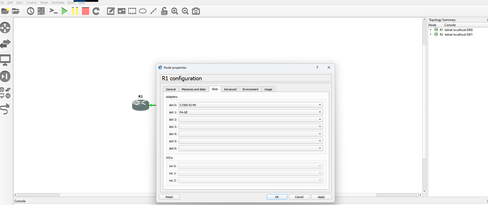
interface with a Gi/Te capable one if you'd like. To change the interface of the router in GNS3, right click on the router you are wanting to change, select Configure
(should be the top option), and go to Slots. It should look like this:
- Power on both routers
Step 3: Configuring Interfaces and IPs
We'll assign IP addresses to the interfaces on both routers to enable communication.
Router1:
- Open the console for R1.
- Enter the following commands:
R1#enable
R1#configure terminal
R1(Config)#interface GigabitEthernet1/0
R1(Config-if)#ip address 10.0.12.1 255.255.255.252
R1(Config-if)#no shutdown
R1(Config-if)#exit
Explanation: This assigns the IP
10.0.12.1/30 to the interface and brings it online.
Router2:
- Open the console for R2.
- Enter the following commands:
R2#enable
R2#configure terminal
R2(Config)#interface GigabitEthernet1/0
R2(Config-if)#ip address 10.0.12.2 255.255.255.252
R2(Config-if)#no shutdown
R2(Config-if)#exit
-
Verify Connectivity:
- From R1, ping R2

- Now from R2, ping R1
 Expected Result: Successful replies indicate the link is working and both devices are reachable.
Step 4: Configuring eBGP
We'll now configure eBGP between our two routers. Router1 is in AS65000 and Router2 is in AS65001, advertising distinct networks.
Router1 (AS 65000):
- Open the console for R1.
- Enter the following commands:
R1#enable
R1#configure terminal
R1(config)#router bgp 65000
R1(config-router)#bgp log-neighbor-changes
R1(config-router)#neighbor 10.0.12.2 remote-as 65001
R1(config-router)#network 192.168.1.0 mask 255.255.255.0
R1(config-router)#exit
R1(config)#exit
Explanation:router bgp 65000- Starts the BGP process for AS 65000.neighbor 10.0.12.2 remote-as 65001- Establishes an eBGP session with R2 in AS 65001.network 192.168.1.0 mask 255.255.255.0- Advertises the 192.168.1.0/24 network into BGP.
Router2 (AS 65001):
- Open the console for R2.
- Enter the following commands:
R2#enable
R2#configure terminal
R2(config)#router bgp 65001
R2(config-router)#bgp log-neighbor-changes
R2(config-router)#neighbor 10.0.12.1 remote-as 65000
R2(config-router)#network 192.168.2.0 mask 255.255.255.0
R2(config-router)#exit
R2(config)#exit
Explanation:router bgp 65001- Starts the BGP process for AS 65001.neighbor 10.0.12.1 remote-as 65000- Establishes an eBGP session with R1 in AS 65000.network 192.168.2.0 mask 255.255.255.0- Advertises the 192.168.2.0/24 network into BGP.
Step 5: Verifying BGP Configuration
We'll confirm our eBGP adjacency is established between the two routers and check the neighbor state.
-
On both R1 and R2, run
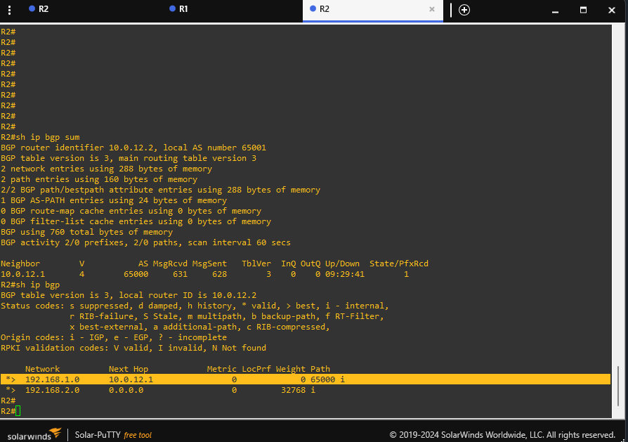
show ip bgp summary:
R1# show ip bgp summary
R2# show ip bgp summary
Expected Result: The State/PfxRcd should be in an '1' state, indicating one prefix has been learned with this neighbor.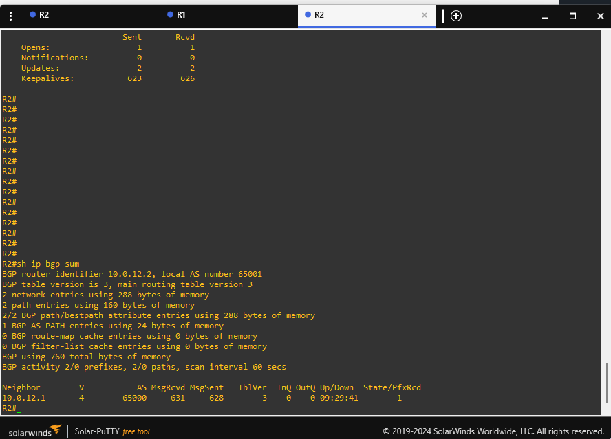
-
If the state is stuck in "Idle" or "Active", verify:
- The IPs under "neighbor" statements match your link addresses ie: 10.0.12.x
- Your AS numbers are correctly configured on each router.
- No firewalls or ACLs are blocking TCP port 179 (since BGP uses TCP).
Step 6: Verifying Routes
Once BGP is established, each router should see the other’s advertised network.
-
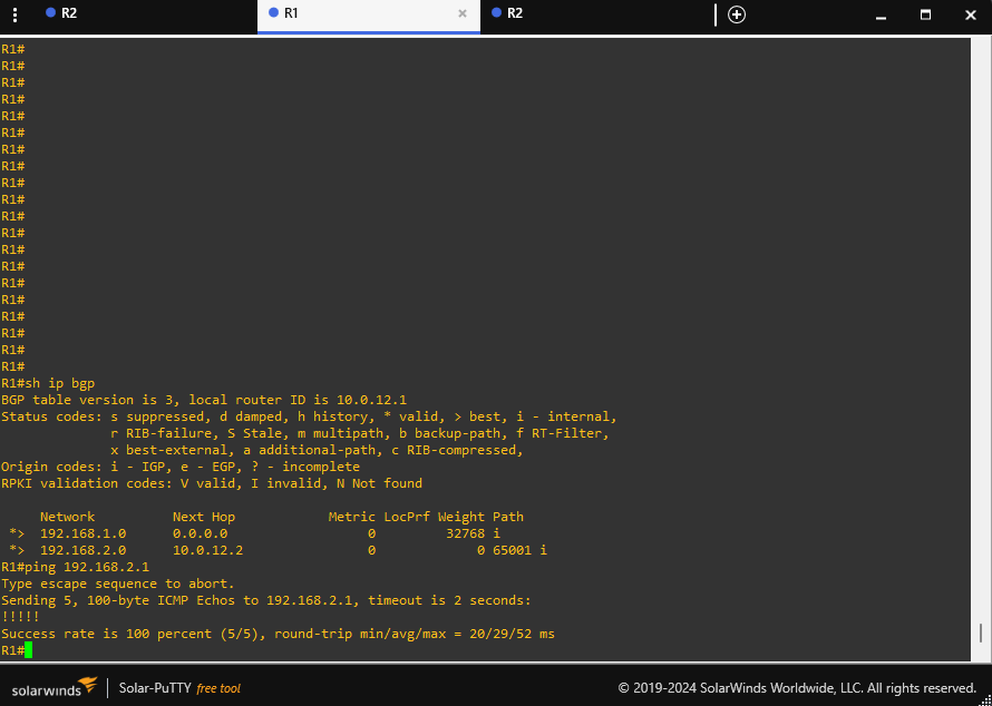
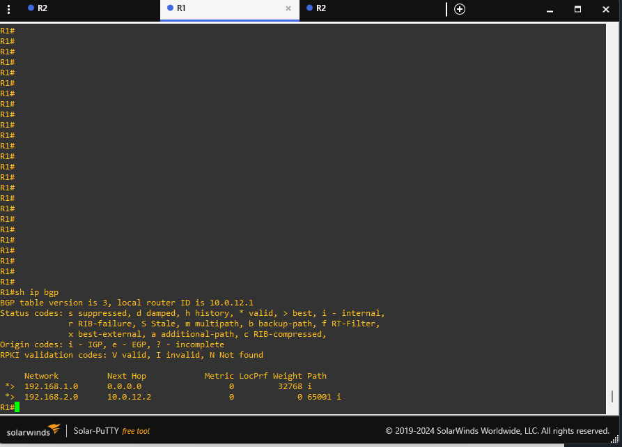
On R1, run
show ip bgp:R1# show ip bgp
Expected Result: R1 should see192.168.2.0/24(or whichever network you have R2 advertising). - On R2, run
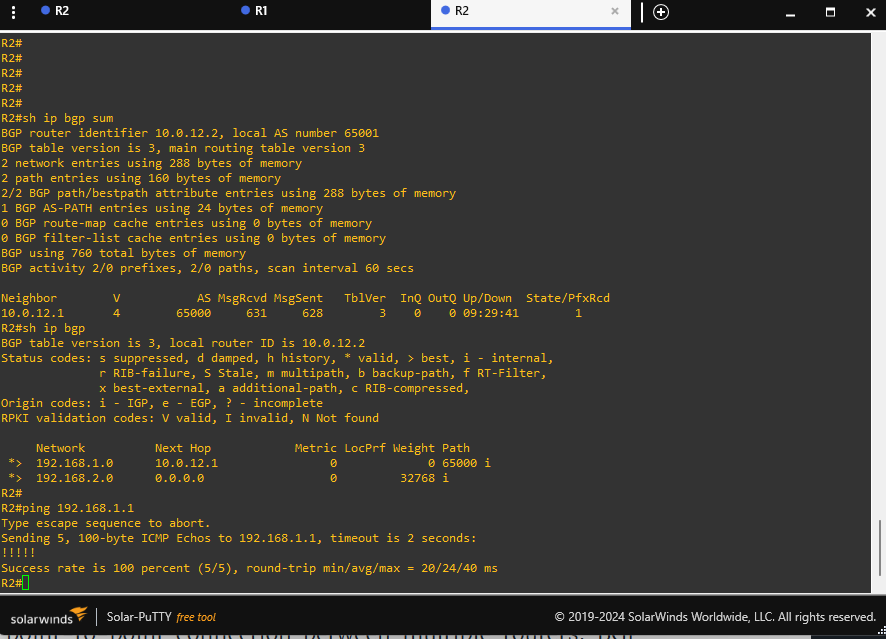
show ip bgp:R2# show ip bgp
Expected Result: R2 should see192.168.1.0/24(or whichever network you have R1 advertising). -
Ping the advertised networks:
- From R1, ping an IP in R2’s advertised subnet
ping 192.168.2.1
- From R2, ping an IP in R1’s advertised subnet
ping 192.168.1.1
- From R1, ping an IP in R2’s advertised subnet
Finished!
Nice! You just completed the eBGP project and should now have a pretty solid understanding as to how an eBGP connection works, how to configure BGP for a point-to-point connection, BGP troubleshooting, route advertisement, and real-world routing scenarios.
If some parts felt tricky, don’t sweat it that’s how you know you’re learning. What's important is that each step forced you to dig deeper into routing concepts like basic IP setup, BGP neighbor relationships and route verification. At the end of the day it's hands-on practice that sets you up for bigger labs, more advanced features, and even real-world implementations down the line.
I would highly recommend going through and retrying the lab. Each new attempt, try to challenge yourself and expand your learning. Try new topologies, throw in extra routers, or explore features like route filters and authentication. GNS3 is super useful with a ton of capabilities, so I challenge you to see what else you can build on top of this foundation. Don’t be afraid to break things! That’s half the fun (and most of the learning!) in a virtual lab environment!
Congrats on seeing this project through to the end. You’re walking away with new skills, a better understanding of BGP, and a sweet setup you can keep expanding on. Keep experimenting, keep learning, and be proud of your newly acquired experience!